
HVAC Symbols PDF: A Comprehensive Guide
HVAC systems, encompassing heating, ventilation, and air conditioning, rely on standardized symbols for design and documentation; readily available PDF charts simplify understanding.
HVAC – Heating, Ventilation, and Air Conditioning – systems are fundamental to modern building design, ensuring comfortable and healthy indoor environments. Understanding these systems requires familiarity with a specialized visual language: HVAC symbols. These standardized representations of components, like furnaces, ducts, and compressors, are crucial for engineers, technicians, and designers to interpret blueprints and schematics effectively.
PDF documents serve as excellent repositories for these symbols, offering easily accessible and shareable resources. They consolidate a wide range of graphical representations, streamlining the design process and minimizing ambiguity. Mastery of HVAC symbols isn’t merely about recognizing shapes; it’s about comprehending the functionality and interconnectedness of entire climate control systems. Proper interpretation is vital for accurate installation, maintenance, and troubleshooting.
What is HVAC? (Heating, Ventilation, and Air Conditioning)
HVAC stands for Heating, Ventilation, and Air Conditioning. It’s a comprehensive system designed to control temperature, humidity, and air quality within a defined space. Heating provides warmth in colder climates, while air conditioning cools spaces during warmer periods. Ventilation introduces fresh air, removing stale air and pollutants, crucial for indoor air quality.
Understanding HVAC requires interpreting technical diagrams, where standardized symbols represent each component. These symbols, often compiled in PDF format, are essential for technicians and engineers. A PDF chart provides a quick reference guide, ensuring consistent interpretation across projects. Correctly deciphering these HVAC symbols is paramount for effective system design, installation, and maintenance, ultimately impacting comfort and energy efficiency.

The Importance of HVAC Symbols
HVAC symbols are critical for clear communication in system design, installation, and maintenance. Utilizing standardized symbols, often found in convenient PDF guides, minimizes ambiguity and errors. These visual representations transcend language barriers, enabling collaboration among diverse teams. A comprehensive PDF symbol chart ensures everyone interprets diagrams consistently.
Accurate interpretation of HVAC symbols is vital for safety and efficiency. Incorrectly identifying a component can lead to improper installation or repairs, potentially causing system failures or hazards. PDF resources offer readily accessible references, streamlining troubleshooting and reducing downtime. Mastering these symbols empowers professionals to effectively manage complex HVAC systems, optimizing performance and longevity.

Common HVAC Symbols
HVAC PDF guides detail frequently used symbols for components like furnaces, fans, compressors, and ductwork, aiding in schematic interpretation and system understanding.
Heating Symbols
HVAC PDF resources comprehensively illustrate various heating system symbols crucial for accurate blueprint reading and system design. Furnace symbols typically represent the heat source, often depicted as a rectangular box with airflow indicators. Radiator symbols, used for hydronic heating, are shown as a series of parallel lines or a stylized radiator shape.
Boiler symbols, representing the water-heating component, are often shown as a pot-like shape with connections for water and gas lines. These symbols, consistently presented in PDF charts, enable technicians and engineers to quickly identify heating components within complex HVAC schematics. Understanding these standardized representations is vital for efficient installation, maintenance, and troubleshooting of heating systems, ensuring proper functionality and safety. Detailed PDF guides often include variations of these symbols to represent specific features or configurations.
Furnace Symbols
HVAC PDF documentation consistently depicts furnace symbols as rectangular shapes, representing the appliance’s housing. Airflow direction is indicated with arrows, showcasing supply and return paths. Variations exist to denote different furnace types – gas, oil, or electric – often distinguished by internal component representations within the symbol.
These symbols in PDF charts frequently include connections for ductwork, gas lines (for gas furnaces), and electrical power. Detailed PDF guides may show symbols for specific furnace features like burners, heat exchangers, and controls. Accurate interpretation of these symbols is crucial for understanding HVAC system layouts and performing effective maintenance. Standardized furnace symbols ensure clarity across blueprints and technical drawings, facilitating efficient communication among professionals.
Radiator Symbols
HVAC PDF schematics commonly represent radiators with a series of parallel lines, often resembling a simplified depiction of the radiator’s finned structure. These symbols indicate heat-emitting devices within a heating system. PDF charts differentiate between various radiator types – such as panel radiators, column radiators, or convector radiators – through subtle variations in the symbol’s design.
Connection points for water or steam pipes are clearly marked on the radiator symbols within PDF documentation. Air vent locations are also frequently indicated. Understanding these symbols is vital for tracing the flow of heating fluid throughout the system. Standardized radiator symbols ensure consistent interpretation across different HVAC plans and maintenance manuals, aiding in efficient troubleshooting and repair work.
Boiler Symbols
HVAC PDF diagrams utilize distinct symbols to represent boilers, the core components of hydronic heating systems. A typical boiler symbol often features a rectangular or cylindrical shape, signifying the pressure vessel. PDF charts illustrate different boiler types – fire-tube, water-tube, or condensing boilers – with variations in their symbolic representation. Connection points for fuel supply (gas, oil), water inlet/outlet, and venting are clearly indicated on these symbols.
Safety devices like pressure relief valves and low-water cutoffs are also frequently depicted alongside the main boiler symbol in HVAC PDFs. These symbols are crucial for understanding the boiler’s operation and safety features. Consistent use of standardized boiler symbols ensures clarity and facilitates effective communication among HVAC professionals during installation, maintenance, and repair.
Ventilation Symbols
HVAC PDF schematics employ specific symbols to illustrate ventilation systems, crucial for indoor air quality. These symbols represent components like Air Handling Units (AHUs), fans, and ductwork. Ductwork symbols vary based on shape (rectangular, round) and material, often shown as lines with directional arrows indicating airflow. PDF charts detail different duct fittings – elbows, tees, reducers – each with a unique symbolic representation.
Fan symbols typically depict a circle with blades, indicating airflow direction. AHU symbols are more complex, representing the unit’s overall structure and key components. Understanding these ventilation symbols within HVAC PDFs is vital for interpreting airflow patterns, calculating pressure drops, and ensuring proper system performance. Standardized symbols promote clear communication and accurate system design.
Air Handling Unit (AHU) Symbols
HVAC PDF diagrams utilize distinct symbols to represent Air Handling Units (AHUs), central components of ventilation systems. These symbols aren’t uniform but generally depict a rectangular box representing the unit’s casing. Internal components, like cooling coils, heating sections, and filters, are often indicated with smaller, standardized symbols within the box. Inlet and outlet arrows clearly show airflow direction.
Detailed PDF charts provide variations for different AHU configurations – horizontal or vertical units, with or without mixing chambers. Some symbols include notations for specific features, such as economizer dampers or humidification sections. Correctly interpreting AHU symbols in HVAC PDFs is essential for understanding system functionality and troubleshooting potential issues. These symbols aid in efficient system design and maintenance.
Fan Symbols
HVAC PDF schematics employ standardized fan symbols to illustrate airflow-moving devices within ventilation and air conditioning systems. The most common symbol is a circle with inward-pointing arrows, representing a centrifugal fan pulling air. Forward-curved and backward-inclined fans may have slightly modified symbols, often differentiated by blade curvature indications within the circle. Axial fans, used for high-volume, low-pressure applications, are depicted as a circle with arrows aligned with the airflow direction.
PDF charts often include variations denoting fan drive types – direct-drive or belt-drive – and control mechanisms. Understanding these symbols is crucial for interpreting HVAC system designs. Correctly identifying fan symbols in PDF documentation aids in diagnosing airflow problems and performing effective maintenance. These symbols are vital for clear communication among HVAC professionals.
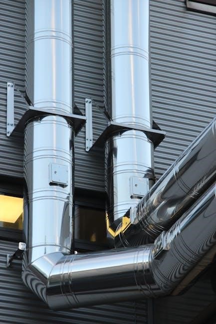
Ductwork Symbols
HVAC PDF diagrams utilize specific ductwork symbols to represent the pathways for air distribution within a system. Straight duct runs are shown as simple lines, while elbows are depicted as curved lines indicating direction changes. PDF charts illustrate various fittings like tees, wyes, and reducers with distinct symbols denoting their function in splitting or converging airflow. Flexible duct is often represented by a wavy line, differentiating it from rigid metal ductwork.
Symbols also indicate duct dimensions and materials. Insulation is shown as a shaded area surrounding the duct line. Understanding these ductwork symbols within HVAC PDFs is essential for tracing airflow paths and identifying potential restrictions. Accurate interpretation aids in system balancing and troubleshooting. These standardized symbols ensure clarity and consistency in HVAC documentation.
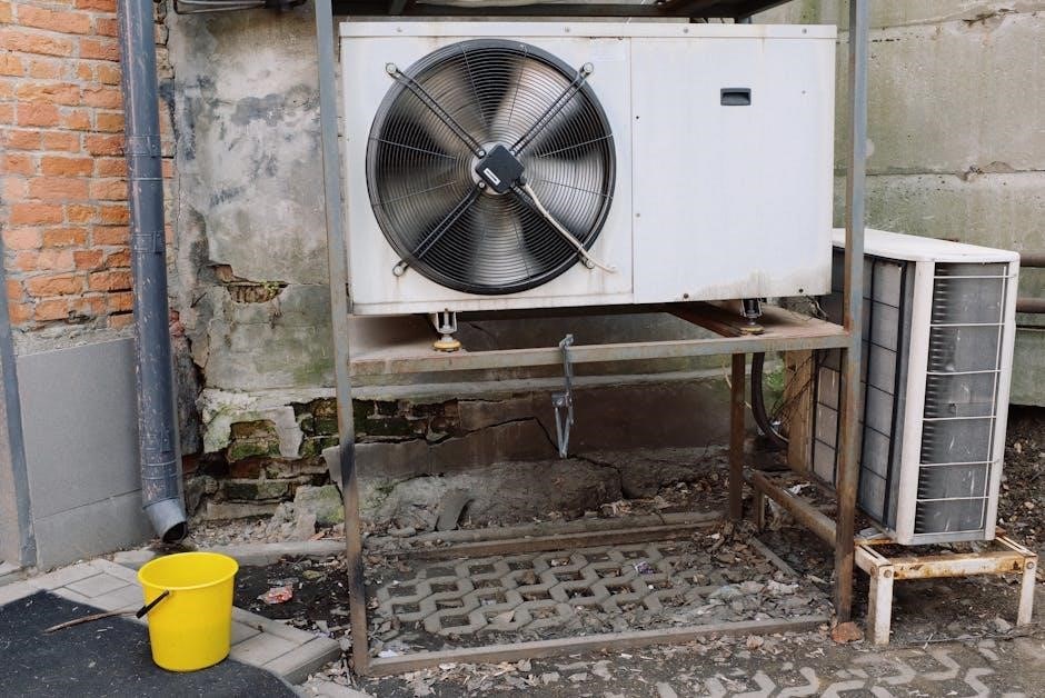
Air Conditioning Symbols
HVAC PDF schematics employ dedicated symbols to illustrate the components of air conditioning systems. Compressor symbols typically represent a sealed unit with inlet and outlet connections, crucial for refrigerant circulation. Condenser symbols depict heat rejection units, often shown with finned coils. Evaporator symbols illustrate the cooling coils where refrigerant absorbs heat from the air.
PDF charts also include symbols for expansion valves, representing refrigerant pressure reduction, and reversing valves, indicating cycle switching. These air conditioning symbols, when accurately interpreted from HVAC PDFs, allow technicians to understand refrigerant flow and system operation. Proper identification aids in diagnosing malfunctions and performing effective repairs. Standardized symbols ensure universal comprehension of HVAC diagrams.
Compressor Symbols
HVAC PDF diagrams utilize specific symbols to represent compressors, the heart of the air conditioning cycle. These symbols generally depict a sealed unit, often rectangular or cylindrical, illustrating the compressor’s function of increasing refrigerant pressure and temperature. Inlet and outlet ports are clearly marked, showing the direction of refrigerant flow.
Variations in symbols may indicate compressor type – reciprocating, scroll, or rotary – though PDF clarity is paramount. Understanding these symbols within HVAC PDFs is crucial for technicians. Correct interpretation aids in troubleshooting refrigerant issues and assessing compressor performance. Detailed PDF charts often include exploded views, enhancing comprehension. Accurate symbol recognition streamlines HVAC system analysis and repair.
Condenser Symbols
HVAC PDF schematics employ distinct symbols for condensers, components responsible for rejecting heat from the refrigerant. Typically, condenser symbols resemble finned coils, often depicted as a series of parallel lines or a rectangular block with radiating lines representing fins. These symbols clearly indicate the heat exchange process.
PDF charts differentiate between air-cooled and water-cooled condensers through symbol variations. Air-cooled units show airflow direction, while water-cooled versions illustrate water inlet and outlet connections. Accurate symbol interpretation within HVAC PDFs is vital for diagnosing cooling inefficiencies. Technicians rely on these symbols to quickly identify condenser locations and assess their operational status. Detailed PDF guides enhance understanding of condenser types and functions.
Evaporator Symbols
HVAC PDF diagrams utilize specific symbols to represent evaporators, the components responsible for absorbing heat from the air. These symbols commonly appear as coiled tubes or rectangular blocks, signifying the refrigerant-to-air heat exchange process. PDF resources often detail variations based on evaporator type – direct expansion (DX) or chilled water.
Understanding these symbols within HVAC PDFs is crucial for troubleshooting cooling issues. Detailed PDF charts illustrate how airflow direction is indicated on the symbol, aiding in system analysis. Technicians use these visual cues to quickly locate evaporators and assess their performance. Correct interpretation of evaporator symbols ensures accurate diagnosis and efficient repairs, as outlined in comprehensive HVAC PDF guides.

Specific Component Symbols
HVAC PDF schematics employ unique symbols for individual parts like filters, dampers, and plenum boxes; these symbols clarify system layouts and functionality.
Filter Symbols

Filter symbols within HVAC PDF diagrams represent crucial components for air quality. Typically, a filter is depicted as a rectangle with parallel lines inside, indicating the filtering medium. Variations exist; some diagrams show a single, thicker line, while others illustrate multiple, closely spaced lines to denote different filter types or levels of filtration.

These symbols are essential for understanding airflow and identifying filter locations within the system. PDF charts often include legends clarifying the specific filter representation used. Understanding these symbols is vital for maintenance, as they pinpoint where filters need replacement. Different symbols might also indicate washable versus disposable filters, aiding technicians in proper servicing. Consistent use of these symbols across HVAC documentation ensures clarity and reduces potential errors during installation or repair.
Damper Symbols
Damper symbols in HVAC PDF schematics illustrate airflow control devices within ductwork. Commonly, a damper is represented as a rectangle bisected by a curved or angled line, signifying its ability to open and close, regulating air volume. PDF charts frequently showcase variations; some depict dampers with arrows indicating airflow direction, while others show multiple sections to represent multi-blade dampers.
These symbols are critical for understanding zoning and airflow balancing within an HVAC system. Technicians rely on these symbols to locate dampers for adjustment during commissioning or troubleshooting. PDF documentation often details damper types – manual, motorized, or pressure-dependent – alongside their corresponding symbols. Accurate interpretation of damper symbols ensures efficient system operation and optimized comfort levels. Consistent representation across HVAC plans minimizes confusion and supports effective maintenance.
Plenum Box Symbols
Plenum box symbols, found within HVAC PDF diagrams, represent distribution points for conditioned air. Typically, a plenum box is depicted as a rectangular or square shape, often with inlet and outlet connections indicated by arrows or smaller connecting lines. PDF resources illustrate variations based on function – supply, return, or exhaust plenums – sometimes using distinct shading or internal markings.
These symbols are crucial for understanding air distribution strategies. A plenum box serves to equalize static pressure and distribute airflow to multiple branch ducts. HVAC PDFs often show plenums connected to Air Handling Units (AHUs) or supply/return ductwork. Correctly interpreting these symbols aids in system analysis and maintenance. Detailed PDF charts may specify plenum dimensions or construction materials alongside the graphical representation, ensuring clarity for installers and engineers.

Resources for HVAC Symbols
Numerous HVAC PDF symbol charts, Visio templates, and online libraries offer comprehensive collections for designers and technicians; aiding accurate system representation.
Visio HVAC Templates
Visio offers a range of pre-designed HVAC templates, streamlining the creation of professional diagrams. These templates contain a library of standardized symbols – representing components like furnaces, air handlers, ducts, and controls – readily available for drag-and-drop functionality. Utilizing these templates significantly reduces drawing time and ensures consistency across projects.
Users can easily customize these templates to match specific system configurations, modifying symbols and adding annotations as needed. Searching within Visio for “HVAC” will reveal various options, catering to different levels of detail and complexity. Furthermore, many online resources provide downloadable Visio stencils containing specialized HVAC symbols, expanding the available library beyond the default options. Properly utilizing these resources ensures accurate and efficient HVAC system documentation, often in easily shareable PDF format.
PDF Symbol Charts
PDF symbol charts are invaluable resources for HVAC professionals, providing a consolidated visual reference of standardized symbols. These charts typically categorize symbols by system component – heating, ventilation, and air conditioning – facilitating quick identification and understanding. Many manufacturers and industry organizations offer free downloadable PDF charts, ensuring accessibility.
These charts are particularly useful for interpreting existing HVAC schematics and drawings, as well as for creating new documentation. The portability of PDF format allows for easy sharing and viewing across various devices. A well-organized PDF symbol chart will include clear depictions of each symbol, along with descriptive labels and potentially, associated technical specifications. Utilizing these charts promotes accuracy and consistency in HVAC system design and maintenance documentation.
Online HVAC Symbol Libraries
Numerous online HVAC symbol libraries offer digital access to a vast collection of symbols, often integrated with CAD and diagramming software. These libraries frequently surpass the scope of traditional PDF charts, providing dynamic symbols that can be easily incorporated into designs. Many platforms offer both free and subscription-based access, catering to diverse user needs.
Benefits include searchable databases, symbol customization options, and compatibility with popular design tools like Visio. Online libraries are continuously updated to reflect industry standards and new technologies. Users can often contribute to these libraries, fostering a collaborative environment. Accessing symbols online streamlines the design process, reducing the need for manual drawing and ensuring consistency across projects. These resources are essential for modern HVAC design workflows.

HVAC System Design & Application
HVAC system functionality, from heating to air conditioning, demands precise design; PDF symbol charts aid in accurate representation and efficient system application.
HVAC System Functionality
HVAC systems maintain comfortable indoor environments through integrated heating, ventilation, and air conditioning processes. Understanding these functionalities is crucial for effective system design and troubleshooting. PDF symbol charts become invaluable tools during these stages, providing a visual language for representing complex components and their interactions.
Proper ventilation ensures air quality, while heating and cooling regulate temperature. These processes often involve components like air handling units (AHUs), fans, ductwork, compressors, and evaporators – all represented by specific symbols in standardized HVAC diagrams. Utilizing these symbols, found within comprehensive PDF guides, streamlines communication between engineers, technicians, and installers, minimizing errors and ensuring efficient system operation. Accurate interpretation of these symbols is paramount for successful HVAC system implementation.
HVAC Manufacturers (e.g., Valeo, Denso)
Leading HVAC manufacturers like Valeo and Denso, renowned in the automotive sector, contribute significantly to advancements in climate control technology. Their systems, detailed in technical documentation often including HVAC symbol guides in PDF format, showcase intricate component arrangements. These PDFs are essential for technicians servicing vehicles equipped with their systems.
Understanding the symbols representing components from these manufacturers – such as compressors, condensers, and evaporators – is vital for accurate diagnosis and repair. Valeo and Denso frequently provide detailed schematics utilizing standardized HVAC symbols, making PDF resources indispensable. Access to these resources ensures proper installation and maintenance, maximizing system efficiency and longevity. Familiarity with these symbols streamlines workflows for professionals working with their products.