Welcome! This manual guides you through utilizing your new smart wristband, a device designed to seamlessly integrate health tracking and smart features into daily life.
Smartwatches and smartbands, initially distinct, now converge in design – a wrist-worn band with a screen, tracking activity, movement, and heart rate using advanced sensors.
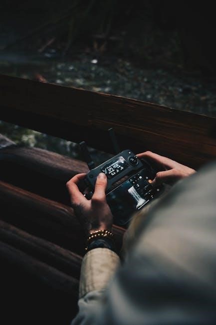
Experience enhanced connectivity with features like camera remote and silent alarms, ensuring you stay productively connected without disturbing others, all day long!
What is a Smart Wristband?
A smart wristband represents a significant evolution in wearable technology, bridging the gap between traditional fitness trackers and fully-featured smartwatches. Initially, smartwatches and smartbands differed considerably, but modern iterations share a core design: a comfortable band worn around the wrist, incorporating a digital screen for displaying information;
These devices utilize integrated sensors to meticulously monitor a diverse range of metrics. Key among these are activity levels – tracking steps taken, distance covered, and calories burned – alongside continuous heart rate monitoring. This data provides valuable insights into your daily activity and overall cardiovascular health.
Beyond basic fitness tracking, smart wristbands offer ‘smart’ functionalities, enhancing convenience and connectivity. These include receiving call and message notifications directly on your wrist, allowing you to stay informed without constantly checking your smartphone. Furthermore, features like silent alarms ensure a gentle wake-up, minimizing disturbance to others.
Essentially, a smart wristband is a compact, wearable computer designed to empower you with data and streamline your daily routine.
Key Features and Benefits
Your smart wristband boasts a comprehensive suite of features designed to enhance your wellbeing and streamline your daily life. Core benefits include precise heart rate monitoring, with reported sensitivity ranging from 87.33% to 88.00%, providing reliable cardiovascular data.
Detailed activity tracking accurately records your steps, distance, and calories burned, motivating you to achieve your fitness goals. Crucially, accurate sleep monitoring requires a snug fit, ensuring detailed analysis of your sleep patterns.
Beyond health, enjoy convenient smart features like a camera remote for effortless photo capture and silent alarms that wake you discreetly without disturbing others. Stay connected with call and message notifications delivered directly to your wrist.
Personalization options further improve performance, and regular firmware updates ensure your wristband remains optimized. Experience a seamless blend of health, convenience, and connectivity!
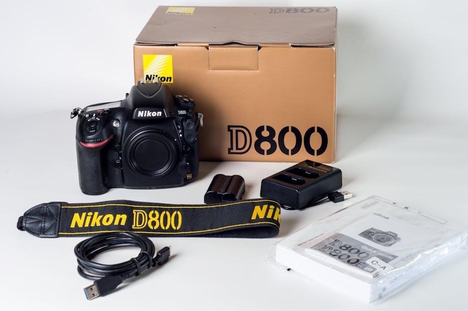
Package Contents
Before you begin, please verify that your package includes all of the following components. This ensures a smooth and complete setup experience for your new smart wristband.
Inside the box, you will find: One (1) Smart Wristband Unit – the core device featuring the sensor array and display screen. Also included is a dedicated Charging Cable, specifically designed for the wristband’s charging port. A detailed User Manual, providing step-by-step instructions and troubleshooting guidance, is also present.
You’ll also receive a Quick Start Guide, offering a simplified overview of the initial setup process. Depending on wrist size, the package may contain Additional Wristband Straps for a customized and comfortable fit. Finally, a Warranty Card outlining the terms and conditions of your product warranty is included for your peace of mind.
If any items are missing or damaged, please contact our customer support team immediately for assistance.

Getting Started: Initial Setup
Let’s begin! This section details the essential steps to power on and connect your smart wristband, preparing it for personalized health and smart features.
Charging Your Wristband
Initial Charging is Crucial: Before first use, it’s essential to fully charge your smart wristband to ensure optimal performance and accurate battery readings. Locate the charging port on your device – consult the ‘Package Contents’ section if you’re unsure of its location.
Connect the provided charging cable to a USB power source, such as a computer USB port or a USB wall adapter (5V/1A recommended). Align the magnetic charging contacts (if applicable) or carefully insert the cable into the port.
A charging indicator will appear on the wristband’s display. The indicator may be a battery icon that fills up as it charges, or a specific animation. Allow the wristband to charge until the indicator shows a full charge;
Charging Time: Typically, a full charge takes approximately 1-2 hours. Do not use chargers with voltages exceeding 5V, as this may damage the device. Once fully charged, disconnect the wristband from the power source. A fully charged wristband provides several days of typical use, but this varies based on feature usage.
Downloading and Installing the Companion App
To unlock the full potential of your smart wristband, you’ll need to download and install the dedicated companion app on your smartphone. This app facilitates data synchronization, customization, and access to advanced features.
App Availability: The app is available for both iOS and Android devices. Locate the app by searching for “[Your Wristband Brand]” in the Apple App Store or Google Play Store. Ensure you are downloading the official app developed by the manufacturer.
Installation Process: Once located, tap the “Install” button. The app will automatically download and install on your smartphone. Grant any requested permissions, such as access to Bluetooth and location services, as these are necessary for proper functionality.
Account Creation: After installation, launch the app and follow the on-screen instructions to create an account. You may be required to provide an email address and create a password. Ensure you remember your login credentials for future access.
Pairing Your Wristband with Your Smartphone
Establishing a connection between your smart wristband and smartphone is crucial for data transfer and feature synchronization. Ensure Bluetooth is enabled on your smartphone before initiating the pairing process.
Initiating Pairing Mode: Open the companion app on your smartphone. Navigate to the “Devices” or “Add Device” section within the app. The app will begin searching for nearby Bluetooth devices; Simultaneously, put your wristband into pairing mode – typically by pressing and holding the function button on the wristband itself. Refer to the ‘Button Functions and Navigation’ section for specifics.
Device Selection & Confirmation: Once your wristband appears in the app’s device list, tap on its name to initiate the pairing process. A pairing request may appear on both your smartphone and wristband. Confirm the pairing request on both devices by selecting “Pair” or “OK”.
Successful Pairing: Upon successful pairing, the app will display a confirmation message. Your wristband is now connected and ready to synchronize data!
Understanding the Wristband Interface
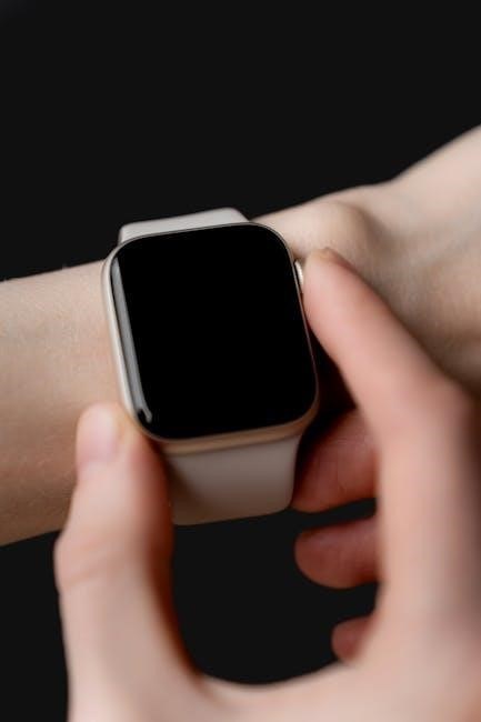
Explore the design! Both devices resemble each other, wrapping around your wrist with a band and featuring a clear screen display for easy navigation.
Display Overview
Your smart wristband features a vibrant display that serves as your primary interface for viewing data and interacting with device functions. The screen showcases essential information such as time, date, and battery level at a glance.
During activity tracking, the display dynamically presents metrics like steps taken, distance covered, calories burned, and your current heart rate. When receiving notifications, the screen illuminates to show incoming call alerts and message previews, keeping you informed without needing to reach for your smartphone.
The display’s brightness automatically adjusts based on ambient lighting conditions for optimal visibility, ensuring readability both indoors and outdoors. Navigating through menus and data screens is intuitive, utilizing simple swipe gestures and button presses. The interface is designed for quick access to your most frequently used features, providing a seamless user experience.
Button Functions and Navigation
Your smart wristband utilizes a combination of physical buttons and touch-sensitive screen gestures for intuitive navigation. A single press of the primary button typically activates the display, allowing you to view the time and date. Holding this button down initiates specific functions, such as starting or stopping an exercise tracking session.
A secondary button, if present, often serves as a ‘back’ or ‘menu’ key, enabling you to navigate through different settings and options. Experiment with short and long presses to discover the full range of functionalities. The wristband’s responsiveness improves with experience, especially with coaching – like swiping faster for quicker menu access.
Combined with screen gestures, button presses offer a streamlined control scheme. Personalization can further boost performance, tailoring the navigation to your preferences. Remember, consistent use will enhance your familiarity and efficiency with the wristband’s control system.
Screen Gestures
Navigating your smart wristband’s interface is enhanced by intuitive screen gestures. A simple swipe up typically accesses notifications, displaying recent alerts from your smartphone. Swiping down often reveals quick settings, allowing you to adjust brightness or activate Do Not Disturb mode.
To move between different screens or menu options, utilize left and right swipes. A tap selects an item, confirming your choice. Long-pressing on the screen may reveal additional options or customization settings. Like learning any new interface, performance improves with practice; participants initially tracked objects slower than with a trackpad.
Experiment with different swipe speeds – faster swipes can accelerate navigation. Personalization plays a key role; adjusting gesture sensitivity can optimize the experience for your individual preferences. Consistent use will quickly make these gestures second nature, providing a fluid and efficient user experience.

Health and Fitness Tracking
Monitor your well-being! This wristband accurately tracks heart rate, activity levels (steps, distance, calories), and sleep patterns, providing valuable health insights.
Ensure a snug fit for optimal data collection.
Heart Rate Monitoring: Accuracy & Sensitivity (87.33-88.00%)
Understanding Heart Rate Data: Your smart wristband utilizes both Photoplethysmography (PPG) and Electrocardiogram (ECG) systems to deliver comprehensive heart rate monitoring. Recent studies evaluating this technology demonstrate impressive accuracy and reliability.
Specifically, wristband PPG readings achieved a sensitivity of 88.00%, a specificity of 96.41%, and an overall accuracy of 93.27%. Wristband ECG readings were also highly accurate, showing a sensitivity of 87.33%, a specificity of 99.20%, and an accuracy of 94.76%.
These results suggest the wristband provides data comparable to traditional 12-lead ECGs. However, individual results may vary. Factors like skin tone, fit, and movement can influence readings. For the most accurate heart rate data, ensure the wristband is worn snugly on your wrist during activity and rest.
The integrated AI algorithm further enhances the accuracy of atrial fibrillation (AF) identification.
Activity Tracking: Steps, Distance, and Calories Burned
Monitor Your Movement: Your smart wristband automatically tracks your daily activity levels, providing valuable insights into your fitness journey. Utilizing built-in sensors, it accurately counts your steps taken throughout the day, motivating you to reach your activity goals.
Based on your step count and personal profile (height, weight, age, gender – entered during app setup), the wristband estimates the distance traveled. This data is presented in miles or kilometers, depending on your preference settings within the companion app.
Furthermore, the wristband calculates an approximate number of calories burned based on your activity level, heart rate, and personal data. While this provides a useful estimate, remember it’s not a precise measurement.
Consistent use and personalization will improve the accuracy of these metrics, helping you understand and optimize your daily activity.
Sleep Monitoring: Ensuring a Snug Fit for Accurate Data
Unlock Restful Nights: Your smart wristband automatically monitors your sleep patterns, providing insights into your sleep duration and quality. It tracks your movements and heart rate throughout the night to differentiate between light, deep, and REM sleep stages.
Accuracy is Key: For optimal sleep tracking accuracy, it’s crucial to wear the wristband snugly – not too tight to restrict circulation, but firm enough to maintain consistent contact with your skin. A loose fit can lead to inaccurate data collection.
The companion app presents your sleep data in easy-to-understand charts and graphs, showing your total sleep time, sleep stages, and any awakenings during the night.
Reviewing this data can help you identify patterns and make adjustments to your bedtime routine for improved sleep hygiene. Remember, the wristband must be worn snugly!
Smart Features and Notifications
Stay Connected: Enjoy convenient features like silent alarms (that won’t disturb others!) and a remote camera control, enhancing your daily productivity and lifestyle.
Silent Alarms
Wake Up Discreetly: The silent alarm feature offers a gentle and personalized way to wake up, vibrating on your wrist without disturbing your partner or others nearby. This is particularly useful for individuals with different sleep schedules or those who need a quiet morning routine.
Setting Up Silent Alarms: Within the companion app, navigate to the ‘Alarm’ section. Here, you can easily set multiple alarms with customized vibration patterns and time intervals. Ensure the wristband is worn snugly during sleep for optimal vibration detection.
Customization Options: Experiment with different vibration intensities to find a level that effectively wakes you without being jarring. You can also label each alarm for easy identification – for example, ‘Work,’ ‘Medication,’ or ‘Meeting.’ Remember to synchronize your settings after making changes within the app to ensure they are reflected on your wristband.
Troubleshooting: If you’re not feeling the vibration, double-check that the alarm is enabled in the app and that the wristband is securely fastened.
Camera Remote Control
Capture Moments Effortlessly: Transform your smart wristband into a convenient remote shutter for your smartphone’s camera! This feature allows you to take photos and videos from a distance, perfect for group shots, selfies, or capturing action sequences where holding your phone isn’t practical.
Pairing and Activation: Ensure your wristband is successfully paired with your smartphone via the companion app. Within the app’s settings, locate and enable the ‘Camera Control’ function. A camera icon will typically appear on your wristband’s display when activated.
Taking Photos: Simply press the designated button on your wristband (refer to the ‘Button Functions and Navigation’ section) to trigger the camera shutter on your phone. The wristband acts as a Bluetooth remote, eliminating the need to touch your phone.
Compatibility: This feature is compatible with most smartphone cameras. However, ensure your phone’s camera app is open and in photo or video mode for the remote control to function correctly.
Call and Message Notifications
Stay Connected on the Go: Your smart wristband keeps you informed with instant call and message notifications delivered directly to your wrist, minimizing distractions from constantly checking your phone. Receive alerts for incoming calls, text messages, and notifications from selected apps.
Configuration via App: Customize notification preferences within the companion app. Choose which apps can send notifications to your wristband, and adjust vibration intensity for discreet alerts. You can typically enable or disable notifications for calls, SMS, and individual applications.
Viewing Notifications: When a notification arrives, the wristband will vibrate and display a preview of the message or caller ID. Swipe on the screen to view the full message (length may be limited) or dismiss the notification.
Important Note: Ensure Bluetooth connectivity between your wristband and smartphone is active for notifications to function correctly. Battery optimization settings on your phone may affect notification delivery.
Advanced Features & Customization
Unlock Full Potential: Personalization boosts performance! Synchronize data for in-depth analysis and keep your wristband updated with the latest firmware for optimal functionality.
Personalization for Improved Performance
Maximize Your Wristband’s Capabilities: The study revealed that personalization significantly boosts performance when using the smart wristband. Initially, participants experienced slower speeds – roughly per minute compared to the average 36 on a smartphone – but consistent use and tailored adjustments led to substantial improvements.
Experiment with different settings within the companion app to find what works best for you. Adjust the sensitivity of the touch screen, customize notification preferences, and explore available watch faces. These seemingly small changes can dramatically enhance your overall experience.
Remember, everyone improves with practice, especially when receiving feedback. Try swiping faster or focusing on continuous writing. The wristband learns from your habits, adapting to your unique style over time. Embrace the learning curve and unlock the full potential of your device!

Data Synchronization and Analysis
Seamlessly Transfer & Understand Your Metrics: Your smart wristband automatically collects a wealth of data – heart rate, activity levels, sleep patterns, and more. To fully utilize this information, regular data synchronization with the companion app on your smartphone is crucial.
The app provides a user-friendly interface for visualizing your progress. Explore detailed charts and graphs illustrating trends in your health and fitness. Analyze your sleep stages, track your daily steps, and monitor your heart rate zones during workouts.
This data-driven insight empowers you to make informed decisions about your well-being. Set personalized goals, identify areas for improvement, and celebrate your achievements. Consistent monitoring and analysis are key to unlocking a healthier, more active lifestyle.
Firmware Updates
Keep Your Wristband Performing at Its Best: To ensure optimal performance, access to the latest features, and bug fixes, regularly updating your smart wristband’s firmware is essential. The companion app will notify you when updates are available.
Before initiating an update, ensure your wristband has sufficient battery life – ideally, over 50%. The update process requires a stable Bluetooth connection between your wristband and smartphone. Do not interrupt the update process, as this could potentially damage the device.
Firmware updates often include improvements to accuracy, enhanced algorithms for health tracking, and new functionalities. Following the update, your wristband may restart automatically. Allow a few minutes for the system to stabilize before resuming normal use. Consistent updates guarantee a smooth and reliable user experience.
Troubleshooting Common Issues
Need Help? This section addresses frequent problems like pairing difficulties, inaccurate readings, and battery concerns, providing solutions for a seamless experience.
Wristband Not Pairing
Experiencing Pairing Issues? Don’t worry, it’s a common concern! First, ensure Bluetooth is enabled on your smartphone and that your wristband has sufficient battery. Confirm the wristband isn’t already connected to another device – it can only pair with one at a time.
Within the companion app, navigate to the “Device” or “Add Device” section and follow the on-screen instructions. If the wristband isn’t appearing in the list, try restarting both your smartphone and the wristband. Sometimes, a simple reboot resolves connectivity glitches.
Ensure the app has the necessary permissions (Bluetooth access) granted in your phone’s settings. If problems persist, “forget” or unpair the wristband from your phone’s Bluetooth settings and then attempt the pairing process again from within the app. A fresh start often yields success!
Finally, verify your smartphone’s operating system is compatible with the wristband and app. Check the app store or manufacturer’s website for compatibility details.
Inaccurate Readings

Concerned about Data Accuracy? Several factors can influence the precision of your wristband’s readings. For heart rate monitoring, ensure the band is worn snugly, but not too tightly, on your wrist. A loose fit can lead to inconsistent data.
Remember, wristband PPG and ECG readings have demonstrated sensitivity of 88.00% and 87.33% respectively, meaning occasional variations are normal. Skin tone, tattoos, and movement during readings can also affect accuracy.
For activity tracking, calibrate the stride length within the companion app for more precise distance calculations. Ensure you’ve accurately entered your personal information (height, weight, age) as these factors influence calorie burn estimates.
Regarding sleep monitoring, a secure fit is crucial. If readings consistently seem off, try restarting the wristband and resyncing data with the app. If issues persist, contact customer support.
Battery Life Issues
Experiencing Short Battery Life? Several factors can impact your wristband’s battery performance. Frequent use of features like continuous heart rate monitoring, notifications, and the camera remote will naturally consume more power.
Ensure Bluetooth is disabled on your smartphone when the wristband isn’t actively syncing. Background app refresh on your phone can also contribute to faster battery drain. Adjust screen brightness within the companion app; a lower brightness setting extends battery life.
Firmware updates often include battery optimization improvements, so ensure your wristband is running the latest version. Avoid exposing the device to extreme temperatures, as this can negatively affect battery health.
If battery life remains significantly shorter than expected, try resetting the wristband to factory settings. If the problem persists, contact customer support for assistance and potential hardware evaluation.